



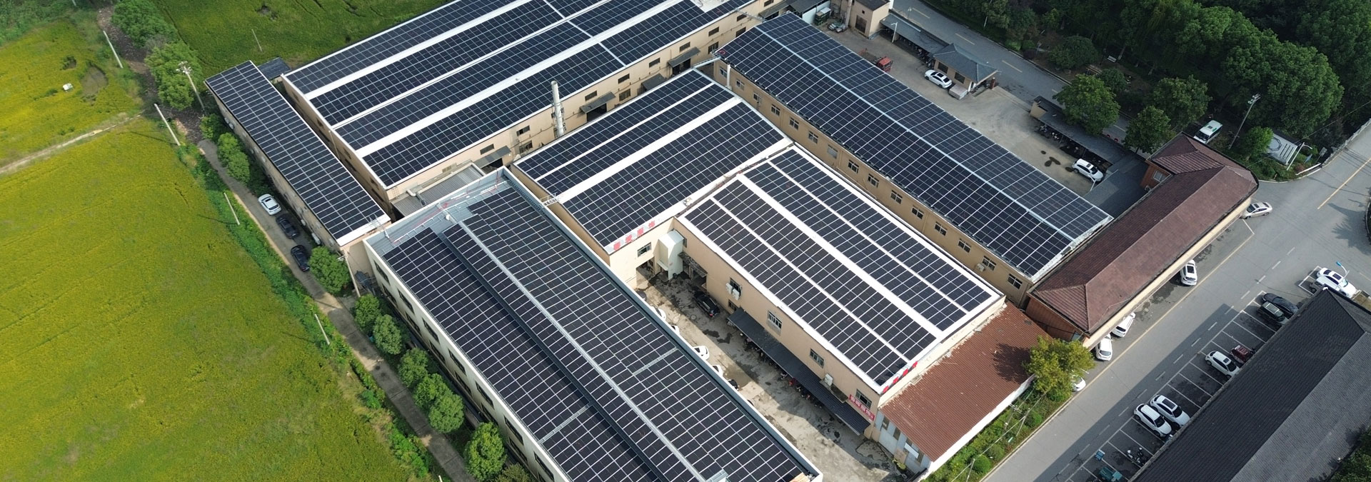
Identifying Metal Roof Areas That Need Flashing Protection
Metal roof sheets shed water well across open runs, yet the building still depends on detailing wherever the sheet stops, turns or is cut. Intersections, edges, openings and structural transitions create paths that rain can follow into the deck or wall if left bare. Roof design—pitch, hip and valley layout, abutments and penetrations—sets where those paths form.
Mapping vulnerable areas before sheet installation determines flashing locations early enough for correct sequencing. Late discovery often forces awkward cuts and reverse overlaps. Identifying the weather lines on drawings and on site is the starting point for every subsequent placement decision.
Installing Flashing Along Roof-to-Wall Connections
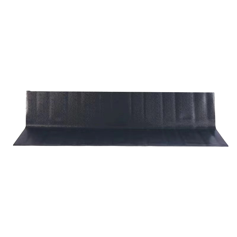
Where a metal roof meets a vertical wall, runoff and wind-driven rain both work at the joint. Wall-related flashing covers the transition between roofing sheets and the wall surface so that water cannot run freely into the gap. The vertical section should sit against the wall (or against the specified under-flashing layer) with enough height for the expected water and snow conditions of the project.
Overlapping arrangements must direct water outward and downward, never back under the sheet or behind the upstand. Apron and counter-flashing sequences, when used, need to match the wall finish so that later cladding does not trap the detail. This abutment line is one of the most leak-sensitive zones on mixed roof-and-wall envelopes.
Placing Flashing at Roof Edges and Eaves Lines
Exposed edges receive weather on both the top face and the cut or folded rim of the sheet. Edge and eave flashing protect those rims, support drip away from fascia and help guide water into gutters or to the intended discharge line. Position relative to the metal roofing sheets follows the system design: some profiles nest into the sheet rib; others cap or underlap according to manufacturer rules.
Suitable edge coverage contributes to protection of the roof structure by keeping water off timber or steel at the perimeter and by reducing lift at sheet ends in wind. Incomplete edge flashing leaves capillary paths and noisy, vulnerable terminations. Drainage planning and edge flashing should be agreed together so that gutters and drips align.
Installing Flashing Around Openings and Roof Penetrations
Pipes, vents, flues and similar penetrations break the sheet plane. Each opening needs flashing—formed sleeves, collars or panel assemblies—that ties the vertical projection back to the roof weathering surface. Shaped sections cover the gap between cut sheet edges and the projecting element so that water running down the pipe or across the roof does not enter the cut.
Integration with the sheet ribs and with any underlay is essential. A collar that sits well on a flat drawing may fight a high rib in the field if the product range was not checked. Proper integration prevents entry around openings through the full service life, including after thermal movement of pipes and sheets. Flashing Panels used at penetrations should be chosen for the geometry of both the roof profile and the service that passes through.
Positioning Flashing in Valleys and at Roof Intersections
Valleys collect water from two slopes and concentrate flow in a narrow channel. That hydraulic load is why valley lines need continuous, correctly lapped flashing or purpose-formed valley gutters compatible with the metal system. Meeting points between roof sections—hips, dead valleys, changes of direction—likewise need coverage that keeps the weather face continuous.
Maintaining unobstructed flow is part of placement: fasteners, debris traps and reverse laps in the valley invert are common failure patterns. Flashing protects the intersection only when water can move through it without ponding against an uphill joint. Design pitch and valley width must match expected rainfall intensity for the site.
Applying Flashing at Ridges and Around Raised Roof Structures
Ridge lines are where two slopes meet at the top. Ridge flashing or ridge caps cover that meeting point and exclude water driven against the crown. Raised roof sections, steps in height and equipment platforms create additional vertical faces on the roof; flashing around those upstands follows the same logic as wall abutments, scaled to the local geometry.
Selected profiles should correspond to the metal roofing system so that ribs, seams and closures engage as intended. A generic flat fold rarely seals a trapezoidal or standing-seam roof without matching accessories. Transition joints along height changes need continuous runs and thoughtful ends so that water cannot track sideways under the cap.
Factors That Guide Placement and Orientation Decisions
Roof slope and drainage direction dictate upslope and downslope laps: water must always run over overlaps, not into them. Metal roof profiles affect both the shape of flashing that will seat correctly and the fastening zones that stay clear of standing water paths. Surrounding walls, parapets and accessories—snow guards, walkways, solar frames—change local flow and may require extra flashing runs or crickets.
A single Flashing Panel type cannot serve every location; edge, valley, ridge and abutment duties differ. Placement plans should list each duty, the product intended for it and the lap rules that apply. Coordination with other trades reduces the chance that late penetrations cut through finished flashing without repair.
Roof Locations and Flashing Intent
| Location | Why flashing is needed | Placement emphasis |
|---|---|---|
| Roof-to-wall abutment | Stops entry at vertical transition | Vertical coverage; outward drainage |
| Edges and eaves | Protects sheet ends; feeds drainage | Drip direction; gutter alignment |
| Penetrations | Seals cut sheets around services | Collar fit to profile and pipe |
| Valleys and intersections | Handles concentrated flow | Continuous channel; clear invert |
| Ridges and raised structures | Closes high joints and upstands | Profile-matched caps; continuous runs |
| Overall plan | Matches slope and profile rules | Overlaps with water flow; trade coordination |
Sequencing Installation with Sheet Work
Some flashings install before adjacent sheets; others cap after. Following the metal roof system sequence avoids trapped reverse stacks. Temporary weather protection during construction should not rely on unfinished junctions through storm seasons. Final inspection along every flashing line after completion catches omitted end stops and damaged corners before handover.
Mapping Flashing to Junctions, Edges and Openings
Flashing on a metal roof belongs at wall abutments, edges and eaves, penetrations, valleys and intersections, ridges and raised structures, always oriented with slope, profile and water flow. Hangzhou Chuanya Building Materials Co., Ltd. produces metal roofing accessories including flashing components for these junction types. Review of roof layout, profile system and drainage design against flashing product ranges supports correct placement and durable weather protection on metal roofs.

 Email:
 Phone:
 Adress:
